This would be more appropriate as a Halloween post, and in fact, that’s what I intially intended, but I want to give you a head start; you need something to do now that Valentine’s Day is over!
I enjoy a jack-o-latern like anyone else; however, candles are consumable and potentially disastrous. I wanted a simple electronic alternative and wiring project. Random flickering is a hard thing to do. Especially without a microcontroller. I decided instead of dimming a light on and off, I’d have some background light, and the overall intensity would be modulated by turning on and off additional LEDs.
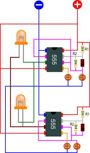
Unfortunately, I can’t find the forum that gave me the idea, but it’s as simple as setting up two 555 timers in astable mode and wiring an LED up in either direction as seen in the wiring diagram below. The diagram includes a modified version of the astable configuration I found in Make: Electronics. The extra diode allows for independent modification of the on and off time by changing and
.
When both output pins (#3) are positive or negative, the LEDs will not light up, however when they are opposite, exactly one of the LEDs will light up (whichever diode is correctly polarized). You can experiment with the resistor and capacitor values to get different frequencies and on/off times. Here are the equations you’ll need; namely, frequency:
on-time:
and off-time:
I hooked this up to +9 V with good results; I noticed that a different input voltage gave me a different response. I didn’t use any resistors in series with the LEDs because my 555 timers were current limited below the LED threshold. My resistors were
each, and the
‘s were each
For capacitors, I had
and less importantly, I also had
. I used electrolytic capacitors because I had them lying around; of course, if you use ceramic capacitors, you need not worry about polarity.
There parameters gave me a frequency of a little less than 8 Hertz, and each was mostly split evenly between on and off (on slightly longer than off). Due to subtle differences in the resistors on each 555 timer (mine were only accurate to +/- 5%), the frequencies will be slightly out of phase. The asynchonous behavior yields a flickering that I found pleasant to the eye. I really haven’t played around with it that much, but it occurred to me that throwing in a photoresistor or something in parallel with one of the resistors could accentuate the randomness. You may also consider using a few potentiometers to make adjustments on the fly.
As I mentioned earlier, in addition to the two flashing LEDs, I had three additional on at all times. Because I didn’t have orange LEDs, I used four yellow LEDs and one red LED to get an orange, flame effect. I used a 9 volt battery to place it outside, inside a jack-o-lantern. For inside, I can place it into a “lantern” and hook it up to a 9 volt DC wall wart.


I would love to make this up (Flickering Flame circuit)
I am not an electronics wiz but I have made up circuits before
I can see the four resistors labeled R1 and R2
I can see the two capacitors
I can see the 555 chips
But what are the two other brown components with the single black stripe?
Thanks
Gordon