So a couple disclaimers before we get started. This is just what I did to accomplish my design goals of controlling AC current; I do not share it for you to copy, but maybe introduce you to some concepts if this is totally foreign to you.
In fact, I do not recommend you trust my circuit. I know for a fact that is not optimally designed, because there are some behaviors that I still do not understand.
What I will say is that don’t work on any AC parts that are plugged in. Keep all AC parts in an insulated box. Do not have low voltage bits physically connected to high voltage bits (i.e. use optical communication when you are ready to run wires out of the box). Plug in your AC to a GFCI outlet and/or use a fuse. Take as many additional safety measures as you can. This stuff is dangerous!
That being said, being able to control AC power is a neat ability to have, and one that I deemed necessary for my project. So I went about figuring out the best way to do it.
A good way to control power in a sort of conservative way is to use a triac. Triacs need a signal in order to allow current to flow in a given direction; and once that current drops below a certain threshold, they stop current flow until receiving another signal. Of course, AC current will drop to zero twice a cycle, so the triac’s default state is to stop current (this strikes me as being a nice “safety” feature); it must continuously receive signals to allow current through.
Now what did I tell you about optical isolation? I chose a MOC3010 to trigger the triac that will be controlling the power to our load. This way I can use a low voltage signal to safely trigger the triac (the power through the triac shouldn’t be able to leak over across the optical barrier, meaning I can safely run the signal wires out of our box to our control hardware).
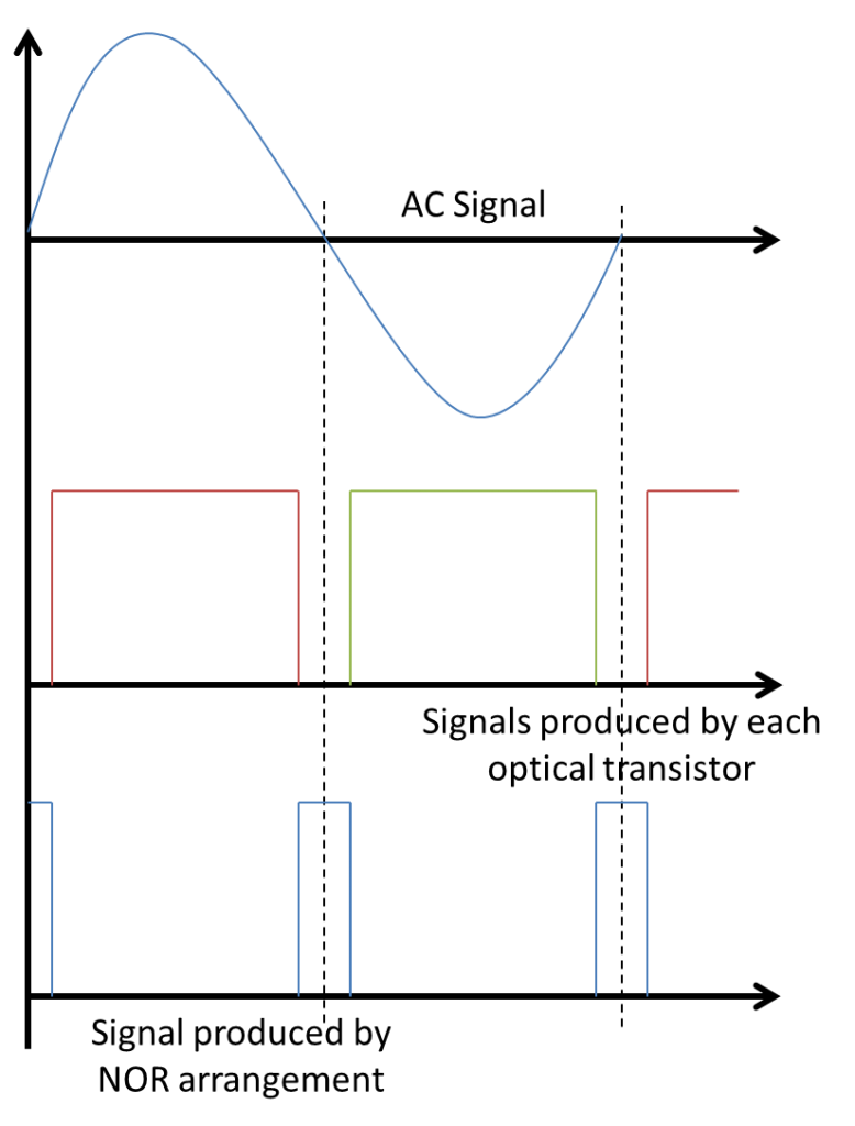
 Okay, so if the triacs need to be triggered every cycle, how do we figure out when cycles are occurring? Let’s continue with the optical isolation theme and make use of two photo-coupled transistors. That is, they behave like NPN transistors, except their base is controlled by a LED hooked up to the AC voltage. So they are only “on” when current is flowing the “right” way; by hooking them up backwards from each other, they will be on at different times in the AC cycle depending on which way current is flowing. But there is a time near the cross-over that the current will not be strong enough in either direction to activate either transistor. By wiring them up in a NOR configuration, we can send a positive pulse indicating the AC current is experiencing cross-over. This is just the sort of information we need to operate the trigger.
One way to handle this would be to setup an interrupt on your microcontroller that will wait to “hear” from the NOR gate. Upon receiving a signal, it would wait some amount of time at the beginning of the half-cycle, and then send a pulse to trigger the triac; the current would then commence flowing for the remainder of the half-cycle. That is, the longer you wait, the less current flows; no wait time would equate to full power.
Quick aside: While waiting 50% of the cycle would result in half power, waiting 90% wouldn’t necessarily result in 10% power. The signal is sinusoidal, and the last 10% of the half-cycle would integrate out to less than half the power.
The main drawback of this approach is that for low power, your code will spend a lot of time in interrupt delays instead of running code. I figured that delays are about as simple a thing as can be done, and I’d just as soon have a dumber piece of electronics take care of it; it’s certainly not something I should make my Arduino stoop to.
So of course, when it comes to out-sourcing timing, my thoughts immediately turn to a 555 timer. In monostable mode, the 555 will output a pulse of a specific length when triggered. By routing the signal through a PNP transitor, we can turn the 555’s positive pulse into a ground signal of finite length during which the triac will be kept off. The pulse length is determined by the product of the values of the capacitor and resistor used in the circuit. So if we can tune this value, we can control the pulse length, hence control the 555 timer pulse length, hence control when in the half-cycle the triac turns “on”, hence control the power through the AC circuit.
*Phew*
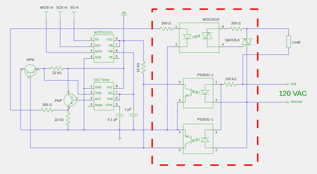
All that remains to be done is to control the product of the values of the capacitor and resistor (our “time constant”). The best way I know how to do this is to use a capacitor with a known value and use a digital resistor (controlled via SPI communication) that can be set with a microcontroller. Bada-bing, bada-boom. Below is a diagram of the final product:
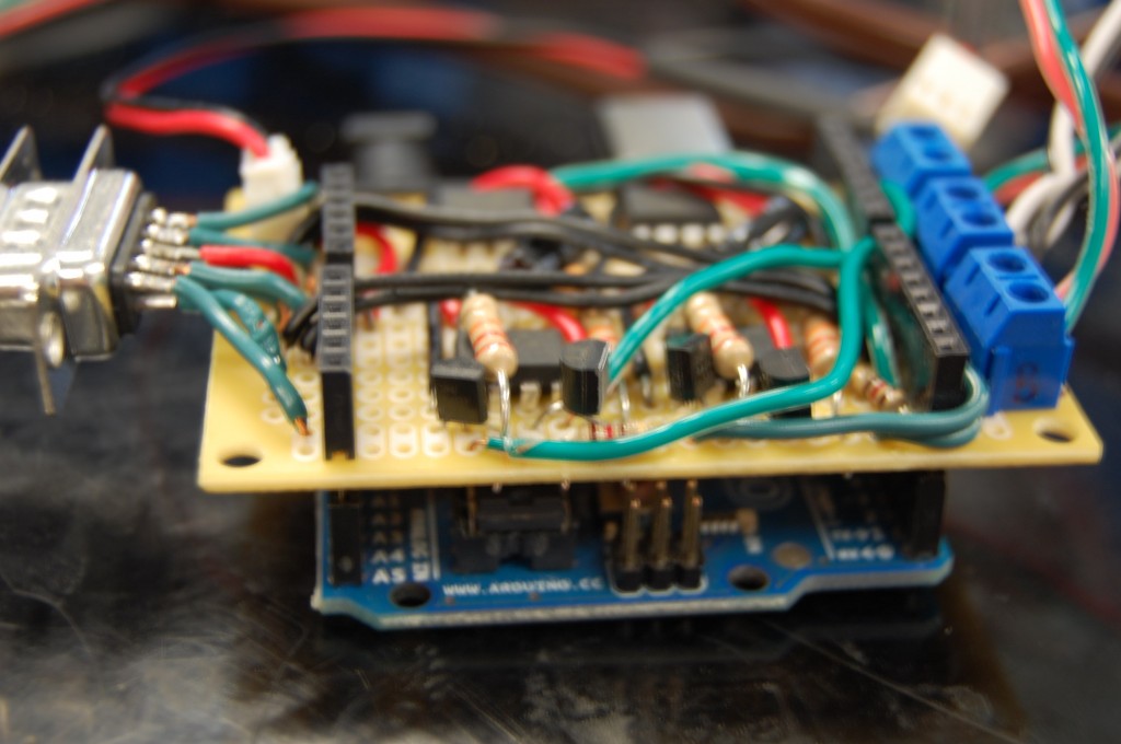
I made a shield for more or less all of the circuitry outside of the red box. Mine is more complicated looking than yours need be because I had two of the circuits to control two power supplies; I also used the shield to communicate with my display box, as well as power a small PC fan I used to cool everything off.
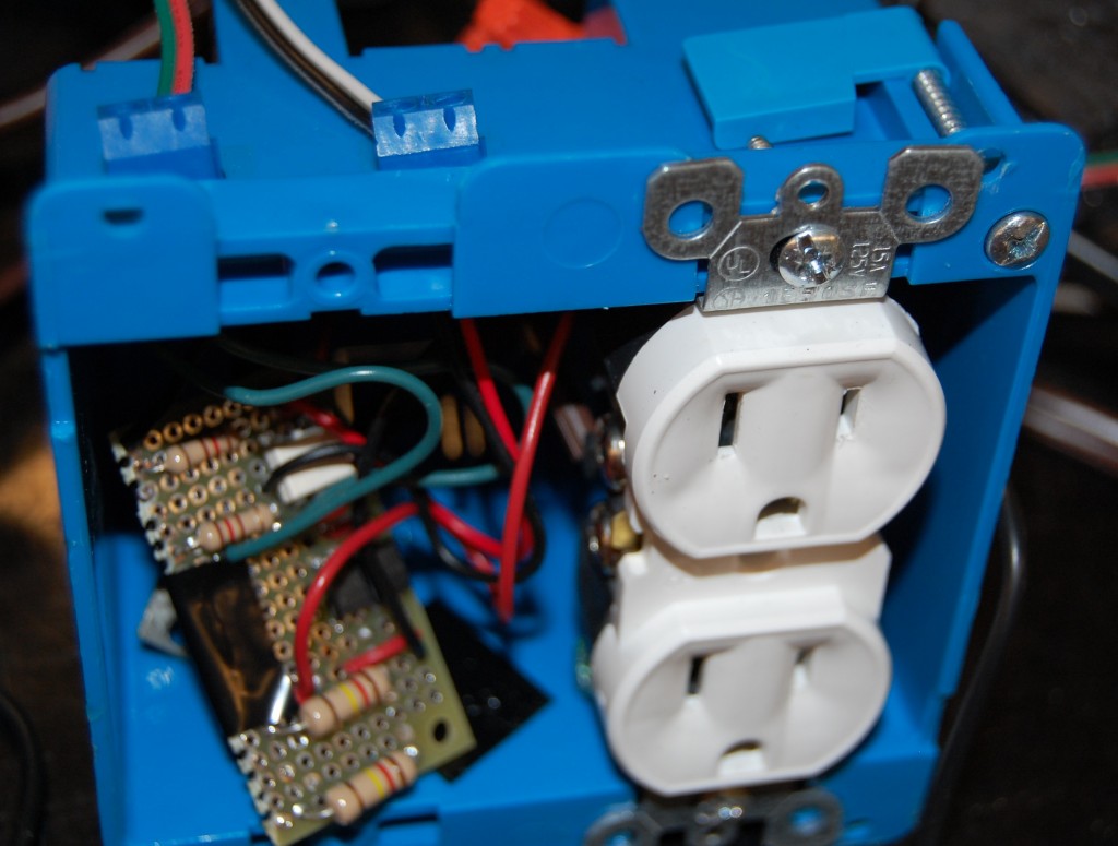
I used a separate board for the “hot” part of the circuit, making sure high voltage bits were not wired too close to neutral bits. The board, plus the triac were tucked neatly alongside the AC power outlet they were wired to (tape was placed on the back side of the board to discourage accidental shorts). Finally, I drilled holes out of the top of the box and wired up the control and +5 V and ground cables out to screw terminals to enable low-voltage communication with the outside world.
I’ve worked out the circuit that I used, but I’m fairly certain there’s a lot of room for improvement. For instance:
- I decided to send a positive pulse indicating the cross-over in the AC signal before I realized that a 555 timer requires a low signal to trigger. So I used a NPN transistor; I would have been better off building an OR gate with the optical transistors and simplifying the circuit.
- One of the PNP transistors I used to “invert” the output pulse of the 555 timer can run quite hot. Hotter than I think is normal or healthy. I’m guessing I could/should have used a resistor between the 555 timer output and the transistor base.
- The delay produced by your capacitor/digital resistor tandem may have to be calibrated within your code to produce desired results due to the variability between capacitors and resistors. You must be careful with the resistor setting at low power, approaching 0%, or else run the risk of accidentally turning on early on the next half cycle instead of late in the current half-cycle.
- After early success, I started having problems with signaling the MOC3010. The output from the PNP was as it should be, but when I hooked it up to the MOC3010, my oscilloscope showed the signal going nutty. I (rightly or wrongly) chalked it up to induced voltages from the AC. I added a 200 ohm resistor just downstream of the PNP. That’s why there are two of them in series; I could probably ditch the one inside the AC box right before the MOC3010.


