Makers and the Internet

It seems like a no-brainer that the internet has been a blessing to makers all over the world.  And I won’t begin to argue that the maker/hacker community is better off without it.  But I will say that for me, the internet has a very real drawback.  And if the internet has taught me anything, it is that if I’m thinking something, a bunch of other people are also thinking, or have already had the same thought.

Which brings me to my point.  While the internet is a great facilitator to provide the information and support I need when trying to accomplish a particular hack, say, the information can be oppressive to my initiative.  For instance, if I have what I consider an original idea that I’m excited to invest time in to make it reality, inevitably, my internet searches reveal that not only has it been done, but it’s been perfected and carried beyond anywhere I had dreamed of taking this.  And thus my enthusiasm is squashed.

Which is probably a personal flaw.  Some sort of form of procrastination, perhaps.  I feel like a horse that needs blinders to run well.  I need the information that will help push my project forward, but will be easily distracted/discouraged by other projects that may or may not be running the same “race” as myself.  And this is a shame, because, oftentimes, the most beneficial outcomes of a project are the lessons learned and ideas generated about someone tangent subjects.

So obviously we already have been told “there’s nothing new under the sun” and “it’s all been done before”, but the internet has forced upon me the paralyzing reality that it’s true.

None of this is to say I’d be better off without it; I just need to learn to get over the fact that I will not ever be doing anything for the first time, or be so passionate about my project that I won’t care if people have done it before and better than me.

Feynman Fysics

Without any new MythBusters popping up lately, I’ve had to find another outlet for my science geek needs.

Fortunately, the library had Feynman’s lectures available, and I’ve got volume one checked out again.  I’ll try to share some thoughts as I relentlessly plow my way through the book.

First off, I’m really enjoying the depth, breadth, and brevity of the topics he covers in such a short time.  It’s neat and depressing how many basic concepts he can walk us through from the ground up; it was definitely “easier” to make multiple really earth-shattering discoveries back in the day.  It feels like most of the low-hanging fruit has been had; of course, we’ll only probably feel that way until the next simple yet elegant discovery is made.

If I were to right an introductory physics text, this is exactly what I would want to do, I just wouldn’t be able to do it.  That being said, I have just a few critiques.

As Dr. Feynman walks the reader through Newton’s laws of dynamics, he isn’t as precise with the notation as I’d prefer.  He is very consistent in his description of vector quantities, but does not distinguish vector values from scalar values in the notation. It is not uncommon to see

 F=m\frac{dv}{dt}=ma.

I mean, granted, LaTeX probably hadn’t been invented, and the type-setting wasn’t too stellar back in 1963, but at least use bold or something to distinguish between scalars and vectors.  This isn’t problematic for the reader already familiar with the concepts, but to new students, I can imagine it will cause at least a modicum of confusion.

In the same vein, he plays kind of loose and fast with units.  For instance, in dealing with the spring equation:

-kx=m\frac{dv_x}{dt}

he understandably wants to simplify it by picking convenient units to eliminate k and m.  So he says that he will use k/m=1.  Okay, but even these have to have some sort of units of inverse time squared; actually, he should have just stated k/m=1\; sec^{-2}, because when he uses the equation later, he uses seconds.  Why is this important?  Because the equation he works with reduces to

\frac{dv_x}{dt}=-x.

Which is problematic, since there are units of acceleration on the left, and distance on the right.  It would have made me feel much better if he had instead written

\frac{dv_x}{dt}=-\frac{x}{sec^2}.

Or something.  Again, it’s not a problem for people comfortable with the material, but may throw some wrenches at somebody still developing mastery.  As opposed to vectors and scalars, he doesn’t really address this inconsistency, which may make it more problematic.

What do you think?  Am I being picky, or are these things to be concerned about?

Controlling AC Power

So a couple disclaimers before we get started.  This is just what I did to accomplish my design goals of controlling AC current; I do not share it for you to copy, but maybe introduce you to some concepts if this is totally foreign to you.

In fact, I do not recommend you trust my circuit.  I know for a fact that is not optimally designed, because there are some behaviors that I still do not understand.

What I will say is that don’t work on any AC parts that are plugged in.  Keep all AC parts in an insulated box.  Do not have low voltage bits physically connected to high voltage bits (i.e. use optical communication when you are ready to run wires out of the box).  Plug in your AC to a GFCI outlet and/or use a fuse.  Take as many additional safety measures as you can.  This stuff is dangerous!

That being said, being able to control AC power is a neat ability to have, and one that I deemed necessary for my project.  So I went about figuring out the best way to do it.

A good way to control power in a sort of conservative way is to use a triac.  Triacs need a signal in order to allow current to flow in a given direction; and once that current drops below a certain threshold, they stop current flow until receiving another signal.  Of course, AC current will drop to zero twice a cycle, so the triac’s default state is to stop current (this strikes me as being a nice “safety” feature); it must continuously receive signals to allow current through.

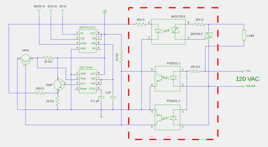
Now what did I tell you about optical isolation?  I chose a MOC3010 to trigger the triac that will be controlling the power to our load.  This way I can use a low voltage signal to safely trigger the triac (the power through the triac shouldn’t be able to leak over across the optical barrier, meaning I can safely run the signal wires out of our box to our control hardware).

AC Signal DiagramOkay, so if the triacs need to be triggered every cycle, how do we figure out when cycles are occurring?  Let’s continue with the optical isolation theme and make use of two photo-coupled transistors.  That is, they behave like NPN transistors, except their base is controlled by a LED hooked up to the AC voltage.  So they are only “on” when current is flowing the “right” way; by hooking them up backwards from each other, they will be on at different times in the AC cycle depending on which way current is flowing.  But there is a time near the cross-over that the current will not be strong enough in either direction to activate either transistor.  By wiring them up in a NOR configuration, we can send a positive pulse indicating the AC current is experiencing cross-over.  This is just the sort of information we need to operate the trigger.

One way to handle this would be to setup an interrupt on your microcontroller that will wait to “hear” from the NOR gate.  Upon receiving a signal, it would wait some amount of time at the beginning of the half-cycle, and then send a pulse to trigger the triac; the current would then commence flowing for the remainder of the half-cycle.  That is, the longer you wait, the less current flows; no wait time would equate to full power.

Quick aside: While waiting 50% of the cycle would result in half power, waiting 90% wouldn’t necessarily result in 10% power.  The signal is sinusoidal, and the last 10% of the half-cycle would integrate out to less than half the power.

The main drawback of this approach is that for low power, your code will spend a lot of time in interrupt delays instead of running code.  I figured that delays are about as simple a thing as can be done, and I’d just as soon have a dumber piece of electronics take care of it; it’s certainly not something I should make my Arduino stoop to.

So of course, when it comes to out-sourcing timing, my thoughts immediately turn to a 555 timer.  In monostable mode, the 555 will output a pulse of a specific length when triggered.  By routing the signal through a PNP transitor, we can turn the 555’s positive pulse into a ground signal of finite length during which the triac will be kept off.  The pulse length is determined by the product of the values of the capacitor and resistor used in the circuit.  So if we can tune this value, we can control the pulse length, hence control the 555 timer pulse length, hence control when in the half-cycle the triac turns “on”, hence control the power through the AC circuit.

*Phew*

All that remains to be done is to control the product of the values of the capacitor and resistor (our “time constant”).  The best way I know how to do this is to use a capacitor with a known value and use a digital resistor (controlled via SPI communication) that can be set with a microcontroller.  Bada-bing, bada-boom.  Below is a diagram of the final product:

wiring diagram

A wiring diagram of my AC circuit. I put the components in the red square in an insulated box.

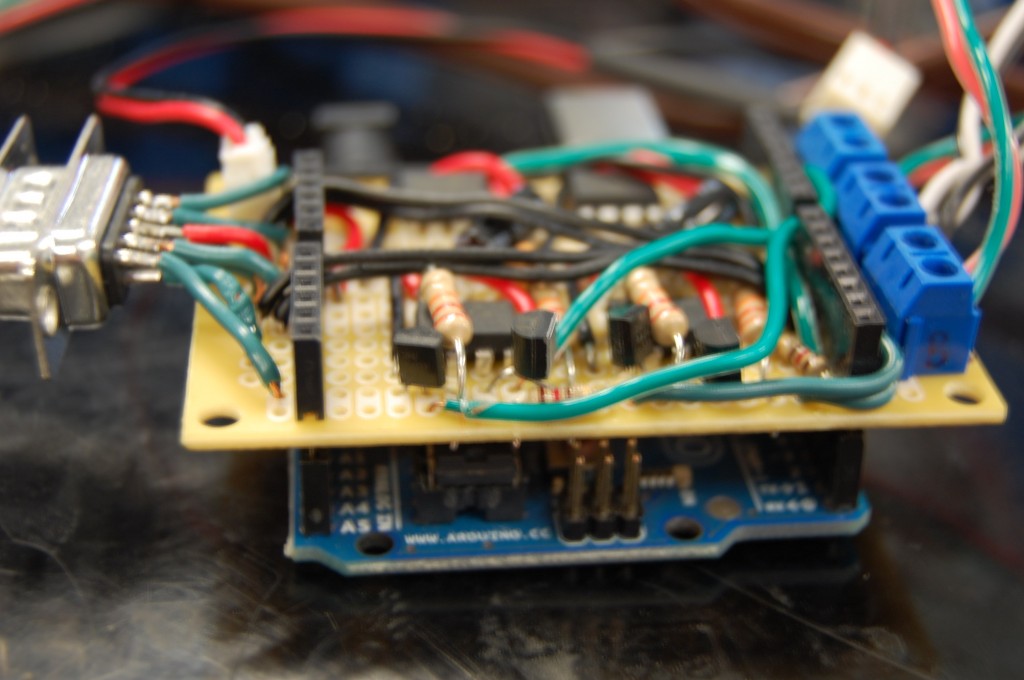
I made a shield for more or less all of the circuitry outside of the red box.  Mine is more complicated looking than yours need be because I had two of the circuits to control two power supplies; I also used the shield to communicate with my display box, as well as power a small PC fan I used to cool everything off.

AC Power Control Shield

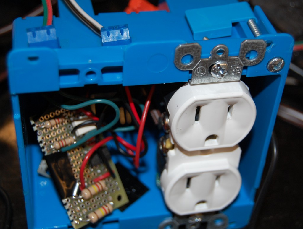
I used a separate board for the “hot” part of the circuit, making sure high voltage bits were not wired too close to neutral bits.  The board, plus the triac were tucked neatly alongside the AC power outlet they were wired to (tape was placed on the back side of the board to discourage accidental shorts).  Finally, I drilled holes out of the top of the box and wired up the control and +5 V and ground cables out to screw terminals to enable low-voltage communication with the outside world.

"hot" box

I’ve worked out the circuit that I used, but I’m fairly certain there’s a lot of room for improvement.  For instance:

  • I decided to send a positive pulse indicating the cross-over in the AC signal before I realized that a 555 timer requires a low signal to trigger.  So I used a NPN transistor; I would have been better off building an OR gate with the optical transistors and simplifying the circuit.
  • One of the PNP transistors I used to “invert” the output pulse of the 555 timer can run quite hot.  Hotter than I think is normal or healthy.  I’m guessing I could/should have used a resistor between the 555 timer output and the transistor base.
  • The delay produced by your capacitor/digital resistor tandem may have to be calibrated within your code to produce desired results due to the variability between capacitors and resistors.  You must be careful with the resistor setting at low power, approaching 0%, or else run the risk of accidentally turning on early on the next half cycle instead of late in the current half-cycle.
  • After early success, I started having problems with signaling the MOC3010.  The output from the PNP was as it should be, but when I hooked it up to the MOC3010, my oscilloscope showed the signal going nutty.  I (rightly or wrongly) chalked it up to induced voltages from the AC.  I added a 200 ohm resistor just downstream of the PNP.  That’s why there are two of them in series; I could probably ditch the one inside the AC box right before the MOC3010.

For the Fourth

I was in my apartment for the 4th of July fireworks this year, but fortunately a local television station simulcasts the fireworks on T.V., so I can watch them from home.  It was a very elaborate show, and they actually have music to which the fireworks are synchronized.  I was very excited when I noticed that when the opened with “Heavy Action” (a.k.a. the MNF theme song) and the music from the T.V. was actually synchronized with the faint reports I was hearing from the actual fireworks!

How is this possible?  Well, ever since Superbowl XXXVIII live broadcasts almost have to have a delay.  So what sort of delay does the feed have to produce this happy coincidence?

As it turns out, according to Google Maps and its “Distance Measurement Tool”, I live about 2 miles from the fireworks ground zero.  The speed of sound in air is strictly a function of temperature (for an ideal gas); it was 66 F (\approx 19 C) according to my external thermometer.  Per Wikipedia:

c=331\tfrac{m}{s}\sqrt{1+\frac{T}{273.15 C}}=331\tfrac{m}{s}\sqrt{1+\frac{19}{273.15 C}}
c=342\frac{m}{s}

So if 2 miles = 3.2 km = 3200 meters, then at 342 m/s, it would take the sound of each firework over 9 seconds to reach me.  This seems like a slightly excessive, but welcome television delay.  Thanks overbearing FCC!  Without you, I would have to actually monitor what my future kids watched on T.V., and I wouldn’t get treated to synchronized fireworks television/noise!

Temperature Controller

Suppose you want to keep something (e.g. a room, sous-vide steak, autoclave) at a certain temperature with, say, an immersion water heater; you could use an off-the shelf temperature controller, OR save some money (but not time), and build your own from the ground up.  If, like me, you’re cash poor, time rich, and intellectually curious, you may consider building one yourself.  I’d say this isn’t a quick build, but I think it is pretty straight-forward.

Bill of Materials:

  • numeric display (x2)
  • potentiometer
  • thermistor or thermocouple
  • 10 K resistor
  • Arduino
  • microSD shield (if you want to log data)
  • AC power control, digital pot/relay, etc…

Let me try to break this down into three parts.  You need something to measure temperature with, something to control temperature with, and some UI to view/control the temperature.

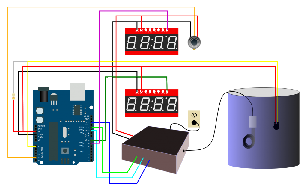
Temperature Controller Schematic

To read the temperature, I went with a thermistor, but a thermocouple would do just as well (sort of depends on the temperature range of your application); it’s just not as easy to get up and running.

For the display, I have found these Sparkfun displays are the best balance of relatively low cost and saving me a lot of pins, wiring, coding, etc. headaches.

Obligatory Disclaimer: AC POWER CAN KILL YOU
For Pete’s sake, be careful, and never handle any circuitry without unplugging everything first.  Use a GFCI outlet; if something goes awry, it will minimize the current going where it isn’t supposed to before cutting off power.

As far as controlling AC power goes, you have a few options, depending on your application and comfort level.  No matter what you choose, I highly recommend making sure the Arduino connections are optically isolated, and the dangerous bits (anything with high voltage) are safely inside a separate, insulated box.  I’d say the easiest way to introduce AC power into your project would be to use a relay of some sort; this gives you limited on/off control, and it is relatively straightforward.  I wanted to be able to control the power level, so my circuit is a little more complicated, turning the AC current on and off every cycle to dial in exactly how much current/power gets delivered.

Okay, so Bildr already has a pretty good page (if I do say so myself) about how to use a thermistor to read temperature; it only takes one analog input (plus power and ground), as well as a resistor.  So that’s easy as pie to setup.

Furthermore, there’s also an article on setting up and using the Sparkfun 4-digit serial display.  I think it’s pretty easy to set up with SPI communication; it minimizes the pins you have to use for one or two displays, and using the NewSoftSerial library for Arduino, you can use any digital pin you want to send SPI communications.  Of course, we don’t care what the board has to say back to us, so you really only need to hook up the transmission (TX) pin to the display’s RX pin.

That only leaves AC power control as the real beast.  I’ll save the gory details for getting under the hood of AC power control for a future post.  For the purposes of this, I literally put a black box into the schematic.

So how to tell the Arduino what temperature to shoot for?  I wired up a potentiometer for each heater I had.  One serial display displayed the current temperature; the other displays a number I control by turning the potentiometer.  At first, I tried simply controlling the “target” temperature, utilizing the Arduino PID library to do the dirty work calculating the power that should be delivered to the heater to reach and maintain the target temperature.

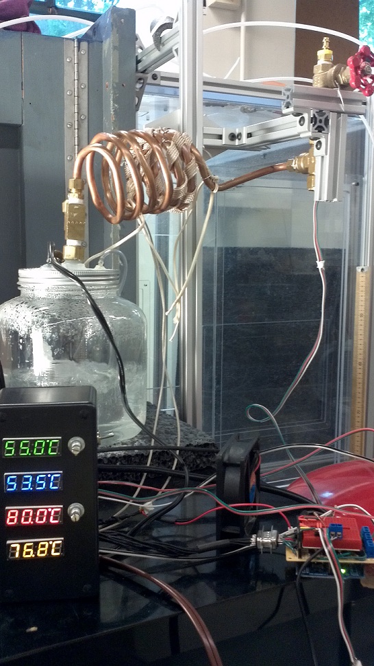
Experimental Setup

Experimental setup of two of the temperature controllers (all displays are of temperature b/c I was still trying PID control)

I don’t think it was a problem with the library, but more with my setup and lacking of proper “tuning” of the parameters, but this type of control didn’t work for me.  So I ended up using the potentiometers to just control the power delivered to my heaters (basically, turning my elegant Arduino AC control into a dimmer).  Then the second displays were just used to output the percent power of AC being delivered.

The last little bit of complexity I added (not shown) was to do some data recording using Sparkfun’s microSD shield (note, it doesn’t come with header pins).  To get it up and running, make use of their Quickstart Guide; it involves downloading a new library and learning a few new commands, but it’s a great shield to mix into your Arduino rotation.

By the time I got everything wired up (and when I use it, I actually double the number of thermistors and heaters, as well as measure the relative humidity), I use nearly all of the Arduino I/O pins.  But I guess that what an Arduino MEGA or 4051 is for.  One thing I did to maximize output while minimizing hardware was to add a flip switch that I would monitor and let it dictate what is output on my serial displays instead of just adding more displays (e.g. an open switch means I’ll output relative humidity; a closed switch, and I’ll send temperature as an output).

22° Halo

22 Halo

I’ve been meaning to post this for quite some time; I’ve had it floating around on my phone; I took it while on a walk on a cold, spring day.  I thought it quite remarkable, but I didn’t know what it was.  Despite the church in the foreground, I was fairly certain its caused could be chalked up to physical, rather than supernatural mechanisms.

Fortunately, Wikipedia was already on the case!  The main ingredient necessary for this phenomenon is hexagonal ice crystals.  When aligned perpendicular to sunlight, visible rays passing though two (non-adjacent, non-opposing) faces will deflect light approximately 22 degrees.

Since the index of refraction of the ice is actually a function of wavelength, the longer wavelength red light will deflected slightly less than the higher frequency blue light.  Hence, in the picture, you can see the inner part of the halo being redder, and the outer edge as bluer.  This is not unlike the color-dependent refraction responsible for producing the colors in a rainbow.  However, unlike a rainbow, there is no internal reflection of light necessary; hence, the halo appears on the same side of the sky as the sun, where a rainbow appears on the opposite side of the sky.

So, even if it’s too cold for a rainbow, that doesn’t mean there isn’t awesome stuff going on overhead; just be careful not to look too closely to the sun!

Blow Your Own Sail

Now, I don’t know exactly what’s going on, because apparently we’re flying in the face of Newton’s laws
Grant Imahara

So according to the Mythbusters, they violated Newton’s laws in this episode.  Presumably they don’t really believe this, or else they would be on their way to Sweden to accept their Nobel prize.  I have to say, I find it a bit odd that they bring in experts to consult on sound effects, but not physics; rather they let Grant make stuff up.  At least they have enough honesty for him to preface his comments with “I don’t know what I’m talking about”.

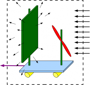
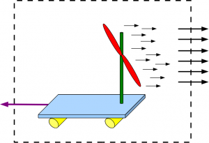
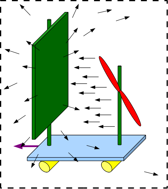
All right, here’s a go at an explanation.  Us fluid dynamicists have a great tool for these types of analyses to keep us from getting all wrapped up in the details: control volume analysis.

\tfrac{\partial}{\partial t} \int \rho \vec{v} dV + \int \rho \vec{v}(\vec{v}\cdot \vec{n})dA=\vec{F}_{ext}

Basically, by looking at the air into a control volume compared to the air leaving a control volume, we can calculate the force on the air in the control volume, and by Newton’s third law, the force on the objects in the control volume.

So a normal sailboat, going with the wind, will “catch” the air blowing into the control volume in the direction of motion, converting the momentum of the air into its own momentum.  In an unmodified swamp boat (or a jet skateboard), air is leaving the control volume in single direction; therefore, there must be a force on the air in that direction; therefore, there must be a force on whatever is moving the air in the opposite direction.  At the end of the day, in both cases air is being accelerated to the right, propelling the craft to the left.

When fan is turned around and the sail is put up, the air is redirected, mostly to the sides.  if the air leaves the control volume more or less equally in all directions in the plane of the sail, the area integral will sum to zero (contributions in opposite directions will cancel each other out).  If the fan is blowing hard enough (and the sail cooperates), I can imagine that the air would be deflected back towards the fan and leave the control volume to the right, resulting in the observed forward thrust.

Note, this also explains why the swampboat was turning wildly, because the air was favoring one side of the sail or the other, and leaving our little control volume in an unbalanced manner; imparting a sideways force.

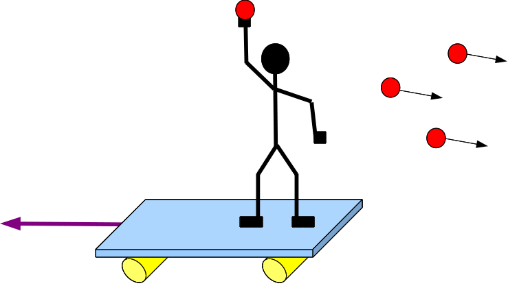
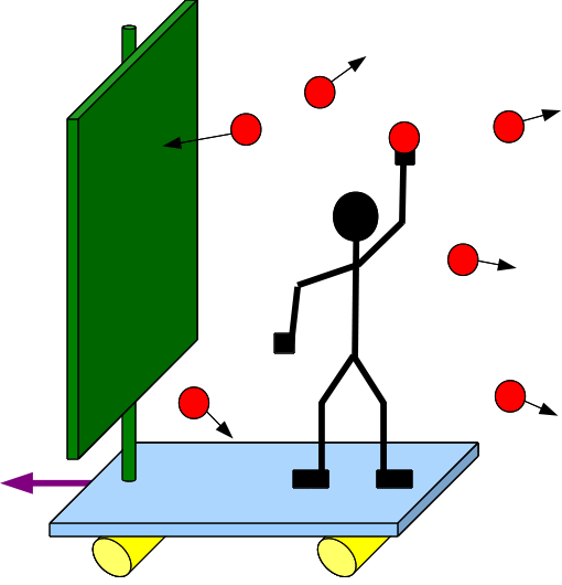
I tried to think of a good non-fluids analogy, and here’s the best I could come up with.  Hopefully, it is relatively intuitive that if you were standing on a skateboard or whatever, and threw tennis balls off of it in a particular direction, you would move in the opposite direction.  Newton says so!  Specifically, conservation of momentum.  In order to maintain your initial zero momentum, the momentum you impart to the balls will be canceled out by your momentum in the opposite direction.

Okay, if you’re still with me, imagine erecting a board on the skateboard, and now throw the balls at the board.  If the board was very sticky, and the balls didn’t rebound (or deflected sideways), then they would have the same velocity as the skateboard, which would have to be zero to maintain the system’s initial zero momentum.  If they reflected perfectly elastically, they would have the same velocity that they were thrown at, completely reversing the acceleration of the skateboard to compensate (this would be equivalent to throwing the balls the other way, straight off of the skateboard).  Say they rebounded less than elastically, or sometimes rebounded to one side or the other; then we’d have a situation more analogous to the fan-powered sail; thrust in the “right” direction, but not nearly as powerful as if the sail wasn’t there.

This isn’t a perfect analogy, because the tennis balls are traveling on the skateboard before they get thrown, whereas the air that the fan is blowing is being pulled from the surroundings.  That being said, since the air is being pulled more or less from all directions, it is not contributing significantly to the thrust.

If the fluid dynamics of sailing is something that interests you, check out how to sail into or faster than the wind!

Move Mod

This is definitely the most invasive hardware hack I’ve ever done; even though it is not particularly difficult, it ended up being quite the undertaking for this noob.  I’ll share a little bit about it to save anyone else who might try something similar some grief.

It all started when the PS Move came out, and I was immediately interested in the possibilities of using it as a gun in a FPS.  Playstation sells a Move Sharp Shooter that will actually remap some of the buttons into more convenient locations, so that one doesn’t have to reach their hand up on top of the gun.  For whatever reason, I didn’t want to hold the front of the rifle with my left hand to control the movement joystick (I think PS did this because if you used the Move before the accessory, you have already gotten used to holding this with your left hand).  Instead, I went with the Battle Rifle.

I quickly became frustrated when I needed to push a button on top of the move (which was frequently; for instance, crouching requires pushing the move button).  I resisted the temptation to buy the Sharp Shooter, and instead started evaluating my hacking options.  With the announcement of Move.Me, I thought Playstation would be making it easier to understand and hack the controller, but they’ve been dragging their feet to really get it started; furthermore, the port that it sounds like the Sharp Shooter uses to remap buttons is, as far as I can tell, quite unique.  I don’t forsee being able to interface with it using a generic male connector any time soon.

So that left cracking the controller open to gain control over the buttons.  I would have been more nervous about it if it hadn’t already been done here and here, leading me to believe it was somewhat straightforward.  Furthermore, pics of the button pads left me optimistic about my ability to simulate button presses independently (basically, all I want to do is close each button’s circuit without using the controller buttons).

Once I got in there, I realized the soldering surfaces I had were much smaller than I anticipated, and any soldered connections would be tiny, and unable to support much stress whatsoever.  I switched from 22 to 28 gage wire.  The picture below shows how I soldered on the left and right side of each pad, as I discovered a button press closed the switch left to right (top and bottom on a give pad were already connected).  I didn’t take the time to be careful about investigating them, but I learned later, unsurprisingly, that the buttons all shared a common ground, so I really only needed to bring out five wires for the four buttons.
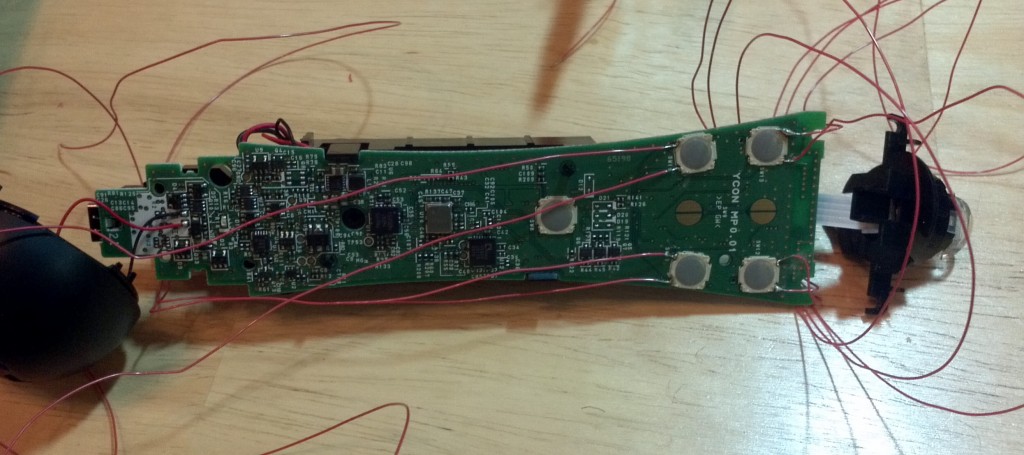
I also soldered wires to each side of the copper semicircles (only the lower two) that are used to register the Move button (as opposed to the four push buttons, the move appears to rely on one of two pieces of conductive material to complete a circuit between either of the pairs of semi-circles).  This had a lot of surface area to work with, but with all of these, I wanted the buttons to still work after I closed it up, so I kept the wires out to the edges of the copper pads.  Not having solder there already made it a little more difficult, but not too bad.  I didn’t care to wire up the bottom pad (PS button) or select/start buttons on the sides, as they’re rarely used during games.
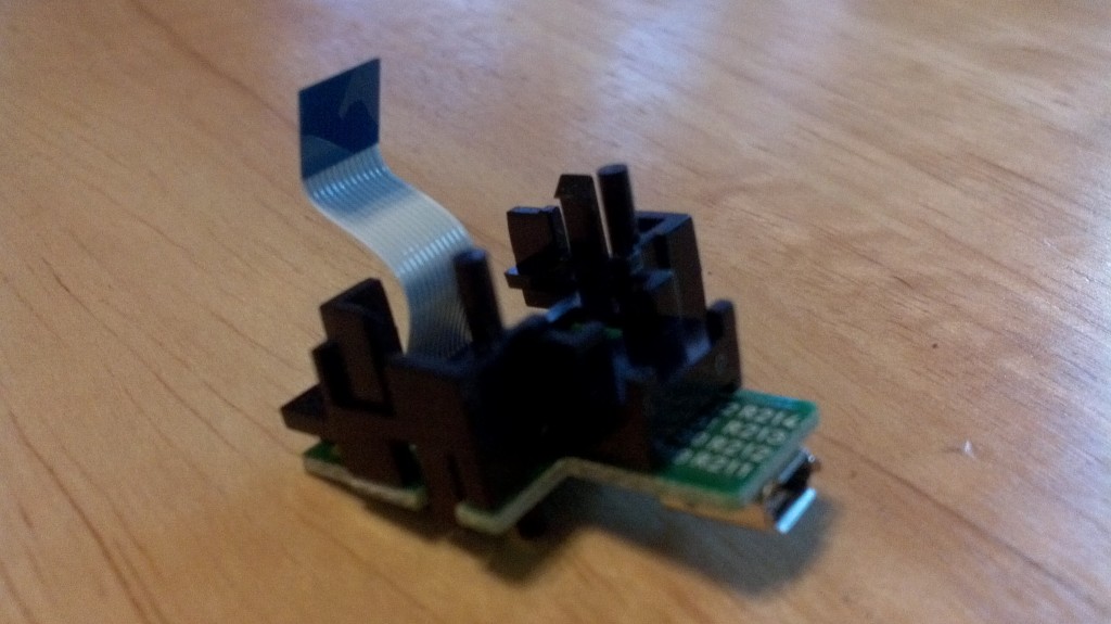
Mystery socket (the appendix/tonsils of the Move)

I had to remove the rear mystery connector; it was part of a little board that had to be unscrewed and unplugged from the rear of the controller (see right).  That left a convenient little hole to run all of my new wires out of.  I carefully strung them out along either side of the board, running them through some holes at the bottom of the circuit board to add an additional point of stress if they got pulled on, so that the solder would not have to bear any appreciable strain.

NOTE: I’ll take a second to say that I do not guarantee or recommend any of the methods I’ve used here.  I’m sure this voids any warranty I had on the controller… Don’t blame me if you attempt something similar and your controller fails to work again or bricks your PS3.  If you are dumb enough to follow my lead, be smarter than me and don’t do dumb things like fail to unplug the battery from the board.  My pinkie tip really got zapped good when I inadvertently used it to close a circuit.  It did not feel good.
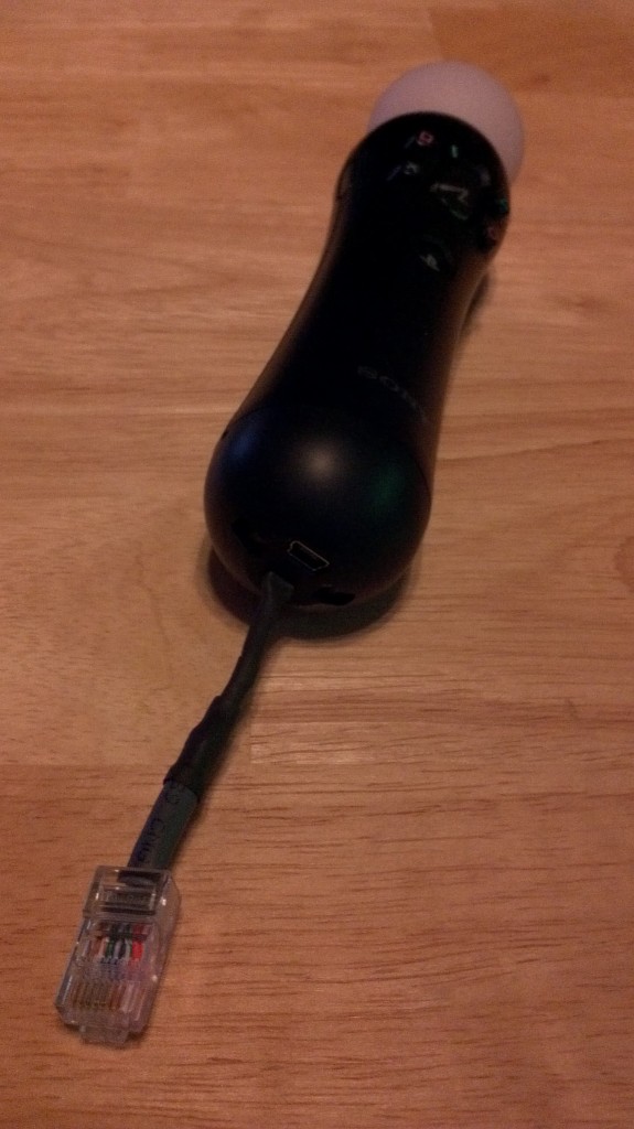
The next part was pretty much the hardest; or at least the most frustrating.  I decided to terminate the wires in something that could easily disconnect from a harness I’d incorporate in the gun’s shell.  I settled on an ethernet cable (RJ45).  If I had a crimping tool, that might have worked well, and probably would have saved me gobs of time.  As it was, I individually soldered each 28 gage wire to the wires from a cut up ethernet plug, each individually shrink-wrapped.  Pain in the ass.  I also wised up and only connected one ground for all five buttons.  Once the black heat shrink has been applied, it actually looks pretty nice and is still very usable otherwise.

I drilled up the gun shell where I wanted my new, red buttons to go, and ran wires through holes I drilled in the gun’s skeleton.  The wires ran to an ethernet socket, where I soldered everything together.  The top of the gun actually had a nice recess that I could tuck the jack in, once plugged into my controller; I left enough slack in the wires that I could pull out the ethernet joint and manually disconnect it if I wanted to use the Move controller for another game or plug it in to charge it up (obviously, I can’t use a charging stand anymore).

All that was left was figuring out which wire corresponded to which button and solder it (plus the ground wire) to the appropriate red button that I subsequently glued (caulked, actually) into the controller.  Pushing either the red or traditional controller button now closes the same circuit and elicits the same response from the PS3.

I definitely made a few mistakes and would do a few things differently next time.  First, I’d like to try crimping into an RJ45 connector.  My remapped square button already isn’t working (fortunately, reloading is gesture-controlled; it’s just really hard to pick up new weapons…).  I suspect my soldered joint failed connecting the ethernet wire, and I’m not about to redo all of those connections (as I would have to if I wanted proper heat shrink on everything).  When all the wires (six of them) come together in the gun cavity, I should have bound them together with tape or zip ties; I’ve already knotted them while pushing in/out the ethernet socket.

I haven’t played too much yet (working on Killzone 3), but I’m definitely enjoying it more than I did before.  I understand it takes several hours of play time to really get used to it, so it remains to be seen how comfortable I will get with my layout.  I’ll probably never know if this suits me better than the Sharp Shooter would; in the meantime, I learned a bit about what makes the controller tick, without comprimising any functionality (except of my pinkie for a couple days).

Blue Ice

We’re trying to make science cool, dude
Tory Bellachi

Wow.  That’s the first show in quite some time that the Mythbusters talked some science and I didn’t get terribly frustrated with them.

The talked about the effect of the boundary layer when guessing why the blue ice stops growing at a certain point.  I touched on boundary layers in a previous post on the Magnus force, and I don’t have a huge problem with anything Grant said.  I’d just like to point out that the boundary layer is not absent over the blue ice; the blue ice has a boundary layer all its own.  It’s just that the boundary layer doesn’t have as much time to grow as it does on the fuselage.  So the shear stress will likely be stronger than it would be if the ice weren’t there.

Also they talked about stoichiometry a bit, which isn’t my strong point, and I can’t verify that the stoichiometric ratio for methane is 9%, but it sounded like they knew what they were talking about.  Being Mythbusters and all, I thought it would have been interesting if they hadn’t trusted the 9% value; I would have liked to see small-scale test results at higher proportions of methane to confirm the blasts actually became less energetic.

Inertia (Which Kind?)

The energy from the bullet’s impact has to overcome the merry-go-round’s inertia
Grant Imahara

The Mythbusters are back and so am I!  Even if I am 6 days late… but still before the next episode!  And it appears they have not hired a science consultant yet; so if they’re busting Hollywood for playing fast and loose with physics (experimentally), then I’m going to set them straight on theory.

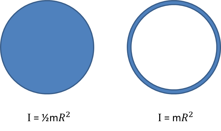
Grant (and the narrator) assume it is the merry-go-round’s inertia (which is related to its mass) that resists being spun by the bullet’s impact.  Rhett Allain actually did a pretty good demonstration of this (actually, his daughters are the ones who did the demonstration).  The mass/weight of the merry-go-round is nearly irrelevant.  Since it is rotating instead of translating, it’s the moment of inertia that is important.  For a given mass, depending on how it’s distributed throughout the merry-go-round, the moment of inertia will vary.

For instance, compare the moment of inertia for a merry-go-round with evenly distributed mass versus all the mass on the outer circumference.  A factor of 2 difference!

So according to the Mythbusters, these two merry-go-rounds have the same inertia, since they have the same mass and will respond the same to a bullet.  I beg to differ.  Depending on how that 500 lbs is distributed it will be easy (if the mass is near the center) or hard (if the mass is near the circumference) to spin.

How will they behave?  We can go about figuring this out in a number of ways.  One simplifying assumption would be to say the bullet gets lodged in the merry-go-round so that we know its behavior before and after impact.

If we knew how long the impact lasted, we could back out the force maybe, and then use the rotational version of F=ma to determine the angular acceleration (and subsequently, the angular velocity) as it relates to torque, \bold{\tau}=\bold{r} \times \bold{F}:

 \bold{\tau}=I\bold{\alpha}

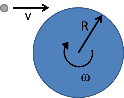
That’s too messy; we only care about the beginning and end states; conservation laws are great analysis tools for that.  I always prefer to solve such things with conservation of momentum when possible.  I’m not sure why; it just seems tidier to me.  Let’s say we conveniently measure the angular momentum around the center of the merry-go-round.  Before impact, the only contribution will be the bullet, which, solving for angular momentum, equals:

 \bold{L}=\bold{r} \times \bold{p}=\bold{r} \times m \bold{v}=Rmv

where R is the radius of the merry-go-round, m is the mass of the bullet, \bold{v} is the velocity (1300 ft/sec) and the direction is perpendicular to the plane of the merry-go-round (down towards the ground).  The merry go round will have the same angular momentum after being hit (before friction slows it down).  It’s angular momentum, I\omega will be the same as the angular momentum before the impact, so

\omega = \frac{Rmv}{I}

See?  Very clean!  C’mon Mythbusters.  You can DO this!

Finally, as an aside, I’ll bet if Jaime and Adam were more committed, and they shaved off their facial hair, those masks would have fit a lot better…